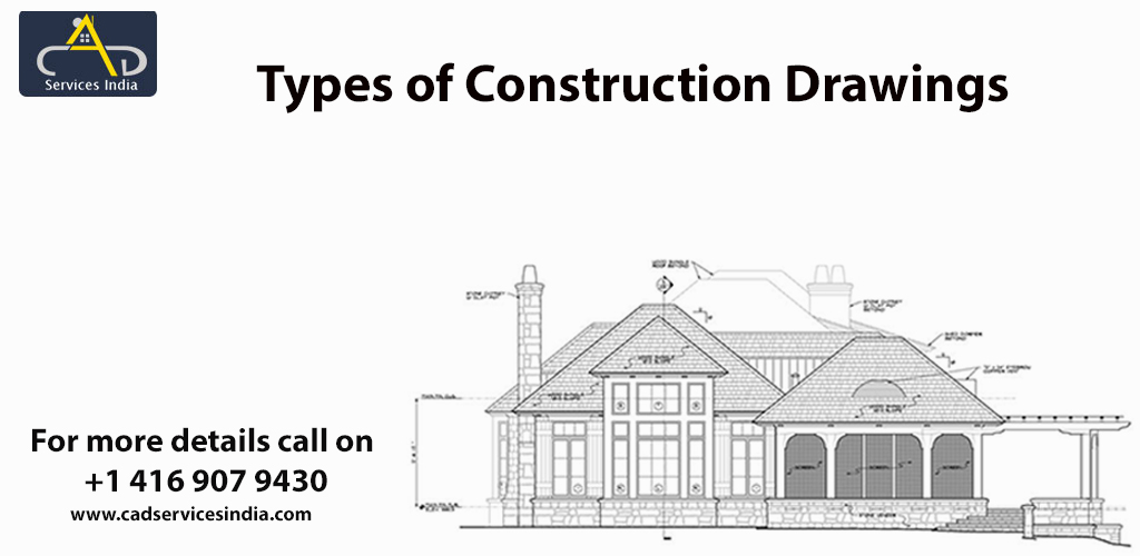
Carrying out construction for any building or a structure is a lengthy process. It requires multiple plans, drawings, documentation etc. in place for the project to kick start. This article aims to highlight certain important drawings prepared for construction process. Each type of drawing serves a different purpose, such as providing technical details about particulars; what is to be built, how will that be built, the materials needed to build the same, measurements and dimensions of all the objects presented in the drawings etc. The main purpose behind producing such drawings is to provide detailed instructions to the on-site workers. Along with this they also play an essential part in getting project approval as these drawings go through various changes, and multiple drafts are prepared before utilizing the final draft in contract to be bid on by contractors. These drawings are produced by the design and technical team, they then become a part of official contract documents and are subject to changes and red lining throughout the project lifecycle. This article would talk about the various kinds of drawings prepared for and during construction process.
Architectural Construction Drawings are prepared by architects in order to convert their design ideas into coherent proposals for clients. These drawings are produced to convey the design intent and concepts about the architecture of the building graphically, provide clarity and understanding about the design, in order to convince clients of design perks, to keep a track record of completed work and multiple other reasons. These drawings are prepared with the help of lines, projections and scale i.e. measurements and dimensions are taken care of and thus these drawings are detail oriented and precise. Architectural construction drawings are relied upon heavily by people working on-site like workers, contractor, electricians, etc. as the architectural structure of the building is built on the basis of this drawing and are used by them for their reference. Thus, these drawings play an extremely crucial role in forming the base for construction of a structure. For certain mammoth projects that require huge manpower and other resources Construction Documentation Services can be availed, so that successful project execution can take place in a considerably faster time span with the help of precise and proficient drawings. Architectural drawings include the following:
Table of Contents
Structural drawing also known as engineering drawing provides information about structural details such as roofs, foundations, strength of different structural elements, structural materials, grade, size and placement of reinforcement, strength of the building and how beams, columns, stairs, slabs etc. are connected. These drawings are prepared by professional engineers and can also be a part of contract approval documentation and in fact an important one in order to ensure that the building is structurally sound. In simpler words, to check the strength of the building. Thus, these drawings cannot be approved without being stamped and signed by a registered professional engineer. Generally structural drawings include the following:
MEP is the abbreviation of Mechanical, Electrical and Plumbing. MEP components are an essential part of any construction project be it residential or commercial. MEP shop drawings are prepared to provide details about various disciplines in mechanical, electrical and plumbing discipline. These drawings are contractor or manufacturers detailed design drawings version. MEP Shop Drawings include guidelines for installation, standards of manufacturing and dimensions of all the components. MEP drawings are coordinated drawings that resolve spatial issues between the MEP components that are to be installed and thereby ensure that there is no interference with the structure of the building. These drawings can also be used as a tool for evaluation of construction permits as they define specific standards to which the subcontractors are supposed to build. The following information is included in these drawings:
These drawings are extremely useful to all the contractors, sub-contractors, manufacturers, suppliers and architects for coordination and installation of various services such as pipes, HVAC ducts, fire protecting sheet etc. and hence as these are coordinated drawings they make sure that there is no interference in the structure of building. Nowadays, because of digital revolution all of these are prepared through AutoCAD by architects and engineers and at times are even outsourced to firms providing Drafting Services in order to avail accurate and detailed drawings for projects having time constraints. BIM software such as Revit and ArchiCAD are also used to generate construction shop drawings.